
Buildings account for 20-40% of total energy use in developed countries. Window shades (or blinds) can help to reduce building energy use and improve visual comfort (i.e., reducing glare and increasing daylighting). A recent study showed that occupants are fairly inactive when operating manual roller shades (O’Brien et al. 2013) which could lead to increased visual discomfort and increased heating and cooling energy use. With aspirations to address issues associated with human inactivity I created an automatic motorized roller shade.
The motor moves the shade position depending on the of the location of the sun and the illuminance (i.e., amount of light) hitting a workplane (e.g., your office desk or kitchen table).
One of the best parts of this instructable is that you do not need to purchase a brand new roller shade to make this work. I will demonstrate how to retrofit an existing manual roller shade into an automatic motorized one using Arduino. The project used Arduino with the Adafruit motor shield to control the interaction between a stepper motor and a digital luminosity sensor.
This Instructable is structured:
- Introduction: What is ‘good’ shade position?
- Required supplies
- Assembly
- Code explanation
- Summary
Step 1: What is ‘good’ shade position?
<imggood’ shade=”” position?”=”” src=”http://cdn.instructables.com/FRM/YCA9/HR0AW9TK/FRMYCA9HR0AW9TK.MEDIUM.jpg” alt=”A solar tracking automatic motorized window blind retrofit using Arduino” title=”A solar tracking automatic motorized window blind retrofit using Arduino”></imggood’>As the sun moves across the sky during the day, where should the shade be positioned? What if it is a very sunny day and there is too much light entering a space causing glare? What if it is an overcast day? This step tries to answer these questions by asking: What is ‘good’ shade position?
In general, we want the shade position to let in as much light as possible without cause any visual discomfort (i.e., maximize daylighting and minimize glare).
The picture above was taken sitting down at my office desk. It was an example of ‘good’ shade position because the shade was positioned so it was blocking direct sunlight yet was still allowing maximum diffuse sunlight to enter into my workspace.
Sunlight can be broken into essentially two components: direct and diffuse. The direct component comes straight from the sun whereas the diffuse component is created when a portion of direct sunlight scatters due to molecules in the atmosphere.
This project aims to control shade position to always block direct sunlight when present and maximize the diffuse component entering the workspace.
Step 2: List of Supplies

Arduino Hardware:
- Arduino Uno (http://www.arduino.cc/)
- Adafruit motor shield (http://www.adafruit.com/products/1438) $19.95
- Headers (http://www.adafruit.com/products/85) $1.95
- Digital Luminosity Sensor (http://www.adafruit.com/products/439) $5.95Stepper Motor:
- Stepper motor with planetary gear box $33.95 (http://www.omc-stepperonline.com/nema-17-stepper-m…)
- Power supply – 12V (May be required if motor cannot produce enough torque through a USB port)Some notes on the stepper motor. You do not need to use this stepper motor and it may be possible to find a cheaper one. But you must consider torque and speed. This stepper motor easily produced enough torque to raise and lower the shade. It moved at a slow, yet smooth (stepping angle of 0.067°), speed because it had a gearbox. You can control the speed of the stepper motor via the code provided but up to a certain point; however, this could create discontinuous motion which could potentially cause the ball chain to skip some gears. High torque and low speed motors work well for this project.3D printed gear:
- 3D printed gear via Shapeways.com ~$15-30 (Discussed in step 2)
- Elastic Band (The thick ones found when buying broccoli work great)Lets discuss the design of the ball chain gear. I searched online to see if I could just the gear that comes with a generic roller shade but I could not find one anywhere. It seems to get one you must buy an entire roller shade.Luckily John Abella created a parametric CAD file of a ball chain gear. The file should be opened with OpenSCAD software.Parametric 3D ball chain gear CAD file by John Abella: http://www.thingiverse.com/thing:12403/#files
OpenSCAD software: http://www.thingiverse.com/thing:12403/#files
The parametric file requires the following inputs that you should measure with digital callipers in mm:
- Motor shaft diameter
- Ball diameter
- Ball count (This is one of the inputs to determine gear radius)
- Ball spacing
- Link diameterJohn Abella has also added code so that different shaft options can be used. The code outputs total height and diameter. Shapeways has limits to the size of the printed piece. I used shaft type #3 to match the stepper motor shaft. I designed the flat spot diameter so that force fit was required to fit the gear onto the shaft. It was difficult to fit the ball chain to the gear correctly even with precise measurements using a calliper. I suggest making the gear diameter large so that you maximize the number of grooves in contact with the ball chain.Attaching a rubber band around the gear increased friction between the ball chain and gear. This should help reduce slippage. Once you are happy with the design ‘compile and render’ the file to type .stl and upload it to shapeways.com or use your own 3D printer for manufacturing. I used the default white nylon material – Strong & Flexible.Tools for assembly:
- Soldering iron (To assemble Adafruit motor shield)
- Clamps (I used quick release clamps)
- Spare wood/platform
- Wires for prototyping
- Electronic breadboard
- Ruler
- Digital Calipers
Step 3: Assembly
Arduino
First assemble the Arduino Motor Shield following the steps in this tutorial: http://learn.adafruit.com/adafruit-motor-shield-v2… Don’t forget to download the Adafruit motor shield code
The wiring schematic and wire colour placement in the above two figures should serve as a reference point to connect your motor.
Digital Luminosity Sensor
The wiring diagrams and code can be found here:
http://learn.adafruit.com/tsl2561/overview
Download both Adafruit libraries: Adafruit_TSL2561 V2 and Adafruit_Sensor
Other software: Arduino Time Library
Download here: http://playground.arduino.cc/Code/time
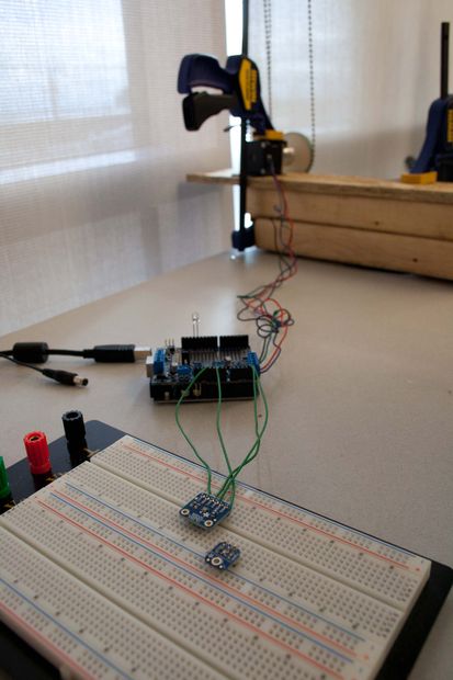
Bringing it all together
The pictures show the fully connected motor and luminosity sensor.
Step 4: Code Explanation
The control strategy used a very similar strategy to Tzempelikos et al. (2013; SC-III) where the shade height was controlled based on the calculated position of the sun and the measured workplane illuminance. Their algorithm was based on open loop procedures which moved shade height to the position where it just blocks direct sunlight from falling on the workplane. The code in this project adopted their open loop aspects and added closed loop control during certain conditions.
The position of the sun is known in terms of its solar altitude (α) and solar surface azimuth (γ). The solar altitude is the angle between the horizon and the sun. The solar surface azimuth is the angle between the outward normal of a surface (e.g., vertical window) and the sun.
My code calculated α and γ based on your location:
- Latitude
- Longitude
- Altitude
- Angle from south to your outward normal of your vertical surface (surface azimuth)The code operates during three periods of conditions depending on these angles:
- The sun is incident on the window surface: α > 0° & |γ| < 90°If the sun is incident on the window surface the first mode of operation is to follow open-loop control to position the shade height calculated using α and γ. If the day has high sky illuminance the workplane illuminance may be greater greater than 2000 lx (lumens/area) when following open loop control. If the workplane illuminance exceeds 2000 lx the roller shade position will enter into closed loop control and overshoot mode will be initiated. This will first cause the shade to lower 2 cm until the workplane illuminance is less than 2000 lx. If the day is overcast, during this scenario, and the workplane illuminance is less than 250 lx and the time is after 9 am the shades will enter into overshoot mode. First the shade will move up 2 cm until the shade height overshoots 2000 lx, then will lower 2 cm so the workplane illuminance is below 200 lx. This is a primitive way to estimate if the day is overcast. Model predictive control could create a smarter control strategy in the future. Once overshoot is triggered the shade will be in closed loop mode for the rest of the day.2. The sun is not incident on the window surface: α > 0° & γ > 90°In this mode the sun is not incident on the window surface so all the light entering the space is diffuse horizontal and ground reflected. The occupants are no longer concerned with blocking direct sunlight and the daylight entering the space should be maximized without causing visual discomfort. The control algorithm adjusts the shade height up or down so that the light level entering the space is always less than 2000 lx.
3. The sun is below the horizontal α < 0°
In this scenario the sun has gone below the horizontal. The blind will fully close for two main reasons: (1) to slightly increase the thermal resistance of the windows and (2) to increase the workplane illuminance when the lights are on because the blinds have a higher reflectivity than the window.
To translate the number of motor step to shade movement you must input properties of your gear:
- Gear ratio
- Motor step angle (degrees)
- Gear radiusThe control strategy program iterated every 10 minutes. This was intended to reduce distractions caused by constantly having the blinds move. The same strategy was adopted by Tzempelikos (2012).Download the code below:
Zibin_ARS_v8.ino12 KB
Step 5: Conclusion
Developing prototypes using Arduino specific to building technology has large potential to substantially reduce energy use in buildings. This project focused on reducing energy in buildings for the lighting and heating/cooling aspect using automatic motorized shades. A manual roller shade was retrofitted into an automatic motorized one that adjusted the shade height based on the position of the sun and/or on the workplane illuminance using open and closed loop control.
Future Work
The project could be easily integrated with a lighting system. In the future the system could also be integrated with an HVAC system in order to minimize cooling and heating loads.
If you enjoyed this instructable please share it with your friends and improve upon it if you wish.
If you have any constructive comments, questions, or suggestions feel free to comment.
Nick Zibin
References
Abella, J. 2010. Ball-Chain Pulley for Polargraph. MakerBot Thingverse. Retrieved from
http://www.thingiverse.com/thing:12403Fried, L. 2012. TSL2561 Luminosity Sensor. Adafruit. Retrieved from
http://learn.adafruit.com/tsl2561
Fried, L. 2013. Adafruit Motor Shield V2 for Arduino. Adafruit. Retrieved from
http://learn.adafruit.com/adafruit-motor-shield-v2…
O’Brien, W., K. Kapsis, & A. K. Athienitis. 2013. Manually-operated window shade patterns in office buildings: a critical review. Building and Environment 60:319-38.
Tzempelikos, A & A. K. Athienitis, 2007. The impact of shading design and control on building cooling and lighting demand. Solar Energy, 81:369-82.
Tzempelikos, A. 2012. Development and Implementation of Lighting and Shading Control Algorithms in an Airport Building. Journal of Architectural Engineering 18(3):242-50
Tzempelikos, A., & H. Shen. 2013. Comparative control strategies for roller shades with respect to daylighting and energy performance. Building and Environment, 60:179-92.